Match the circuit components with their schematic diagrams – Understanding the relationship between circuit components and their schematic diagrams is crucial for electrical engineers and hobbyists alike. This guide provides a comprehensive overview of circuit components, schematic diagrams, and the techniques used to match them effectively.
Schematic diagrams serve as blueprints for electrical circuits, utilizing symbols and lines to represent the connections and functionality of components. By understanding these diagrams, professionals can analyze, troubleshoot, and repair circuits with greater accuracy and efficiency.
Circuit Components Identification
Circuit components are the building blocks of electronic circuits. They are used to control the flow of electricity and perform various functions. Common circuit components include:
- Resistors: Resistors limit the flow of current in a circuit.
- Capacitors: Capacitors store electrical energy.
- Inductors: Inductors store magnetic energy.
- Diodes: Diodes allow current to flow in only one direction.
- Transistors: Transistors are used to amplify signals and switch currents.
Schematic Diagram Representation
Schematic diagrams are graphical representations of circuit designs. They use symbols to represent circuit components and lines to show how they are connected. Schematic diagrams are essential for understanding and troubleshooting circuits.
Common conventions used in schematic diagrams include:
- Symbols: Each circuit component has a unique symbol.
- Lines: Lines connect the symbols to represent the electrical connections.
- Annotations: Annotations provide additional information, such as component values and signal names.
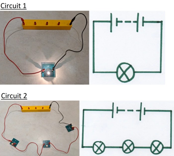
Matching Circuit Components to Schematic Diagrams, Match the circuit components with their schematic diagrams
To identify circuit components on a schematic diagram, you need to know the symbols that represent them. The following table lists common circuit components and their corresponding schematic symbols:
| Circuit Component | Schematic Symbol |
|---|---|
| Resistor |  |
| Capacitor |  |
| Inductor |  |
| Diode |  |
| Transistor |  |
Advanced Schematic Analysis
Analyzing complex schematic diagrams requires a deep understanding of circuit theory and component behavior. Techniques for advanced schematic analysis include:
- Identifying component connections: Determine how components are connected to each other.
- Tracing signal flow: Follow the path of signals through the circuit.
- Identifying potential faults: Look for errors or inconsistencies in the schematic diagram.
Essential Questionnaire: Match The Circuit Components With Their Schematic Diagrams
What is the purpose of a schematic diagram?
Schematic diagrams provide a visual representation of electrical circuits, making it easier to understand their design and functionality.
How do I identify circuit components in a schematic diagram?
Each circuit component is represented by a unique symbol in a schematic diagram. By referencing a component library, you can identify the function and specifications of each component.
What are some common circuit components?
Common circuit components include resistors, capacitors, inductors, diodes, and transistors.
How do I troubleshoot a circuit using a schematic diagram?
By analyzing the schematic diagram, you can identify potential faults, trace signal flow, and determine the root cause of circuit malfunctions.